Yi Song, Yifan Zhang
Indoor localization has been an active research area over the years. Since GPS signal is generally not available in indoor scenarios, researchers have been trying to utilize wireless signals such as Bluetooth or WiFi strength (RSSI) to indicate relative locality. While the wireless signal strength can be affected by lots of factors, the indicated locality could be inaccurate. Google announced in 2018 I/O that Android P would incorporate WiFi Fine Time Measurement (FTM) to enable an accurate distance measurement by round trip time(RTT) of WiFi signal. The advertised precision of measurements was up to one meter which made WiFi RTT a great candidate for future development. In this project, we are characterizing WiFi RTT performance in different testing scenarios and comparing between hardware devices. We also design a Proof-of-Concept application for parking lot navigation using the WiFi RTT. The rest of this report is constructed as follows: from section I to section II, we provide basic introduction and theoretical backgrounds of WiFi RTT; from section III to section IV, we introduce our experiment software and hardware setups; in section V, we analyze our collected data and in section VI, we introduce our Android application for finding car in parking lot. We show future work and conclusion in section VII and VIII.
Indoor Localization; WiFi Round-Trip Time; WiFi Fine Time Measurement; Parking Lot Navigation
WiFi FTM protocol is included in IEEE802.11-2016 with IEEE802.11mc REV. The protocol does not need WiFi devices to be synchronized. Instead, they use round trip time of the WiFi signal to estimate the distance between the devices. In 2017, WiFi Location[1] was announced by WiFi alliance so that it is now a certified official service of WiFi. Then Google incorporated it into the Android API in 2018 and demonstrated the sample app running on Android and claimed it can reach down to one-meter precision[2], far more accurate than RSSI based localization. All these great characteristics made it a great fit for indoor localization when GPS could not reach or not accurate enough. WiFi RTT is now already fused into the Android’s fused location provider and will contribute to localization result of the Android phones when there are data available. Google announced that they will crowdsource the accurate locations of public installed WiFi RTT-capable APs and use them to localize user[2]. Since only the user device knows all the round trip timestamp collected, the public AP will not have information about the users’ location.
Since the protocol is introduced very recently, there are few experiments done and it is hard to find hardware that supports it out-of-box. Many initial verification tests are done on customized WiFi AP products based on Intel chip such as WiFi Indoor Location Device (WILD). We also devices such as Pixel phones and Google WiFi based on Qualcomm chips also support WiFi RTT with some necessary firmware/OS updates. Based on this fact, we are conducting our characterization experiments on Pixel 2 phone, Google WiFis, and WILD APs.
For characterization of WiFi RTT, we collected distance and RSSI data from different environments and different responder devices using the same Pixel 2 phone running the app we developed ourselves. We also made use of multiple APs placed in different locations to characterize localization precision. The app also demonstrated the application of WiFi RTT to direct users finding their cars in a large scale parking lot. The demo video can be found at https://youtu.be/3Qu_qaIWJbA.
In summary, there are two main goals of this project: Characterizing the performance of WiFi RTT incorporated in Android in different environments such as indoor or outdoor using two different responder APs (Google WiFi and WILD). Comparison and data analysis are made between the different environments and different responder APs. Designing a proof-of-concept Android app to enable user getting directions to find their parked car in a large-scale parking lot. The app will demonstrate the future application for WiFi RTT in parking lot scenarios and could be extendable to other settings.
For this project, we created a single app for both data collecting and application demonstration so that we could realize both goals by a single app. The source code for the app can be found in our Github repository (https://github.com/MasterYI814/ECE202_Final_Project/tree/master/Findurcar). Google and WILD AP also provided their sample code for demonstration purpose, which can be found at https://github.com/googlesamples/android-WifiRttScan and https://github.com/Compulab-WILD/WILD-minimal respectively.
WiFi RTT is already verified for high accuracy in prior work[3], the researchers showed high accuracy results in both outdoor and indoor scenarios using an open platform. The concepts of WiFi RTT is shown in Figure.1 below[2].
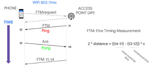
Figure.1 WiFi RTT Mechanism
There are two hardware devices involved in the ranging process: our phone as a slave (station) and the access point as a master (responder). The process has mainly three steps: request, ranging burst and timestamp send-back. The first step is initiated by the phone (slave). An FTM ranging request is sent to the specified WiFi RTT capable access point(s) for acknowledgment. Once the access point accepted the request, the second step took place and the actual ranging process happened during the second step. During the ranging burst, multiple FTM handshake can be initiated by the access point (master). A single FTM handshake is shown in the Figure as “Ping” and “Pong”. The FTM packets will first initiate by the access point to the phone as “Ping”. The access point will record the timestamp it sends the “Ping” as t1, and the phone will record the timestamp when it receives the “Ping” as t2. Then, the phone will send the ACK (“Pong”) back to access point and record the send time as t3. The access point records the “Pong” received time as t4. Finally, the t1, t4 timestamps will be sent back to the phone for calculation. This completes a single FTM handshake, and a burst can include multiple handshakes. The round trip time will be calculated as t_diff = (t4-t1)-(t3-t2). The distance could be calculated as t_diff * c(speed of light). The t_diff calculated from handshakes will be averaged to get a more accurate result for a burst.
The Android RTT API features WiFi location functionality that measures the distance to nearby RTT capable WiFi access points and peer Wi-Fi Aware devices. If measuring the distance to three or more access points, the user can use a multi-lateration algorithm to estimate the device position that best fits those measurements. Google claims that the result is typically accurate within 1-2 meters. The requesting device doesn't need to connect to the access points to measure distance with WiFi RTT. To maintain privacy, only the requesting device is able to determine the distance to the access point; the access points do not have this information. This API is further included in Google’s Fused Location Provider. The fused location provider is a location API in Google Play services that intelligently combines different signals to provide the location information that the user needs. The fused location provider manages the underlying location technologies, such as GPS and Wi-Fi, and provides a simple API that the user can use to specify the required quality of service.
There are some requirements when using the WiFi RTT API. The hardware of the device making the ranging request must implement the 802.11mc FTM standard. The device making the ranging request must be running Android 9 (API level 28) or later. The device making the ranging request must have location services enabled and Wi-Fi scanning turned on. The application making the ranging request must have the ACCESS_FINE_LOCATION permission. The access point must implement the IEEE 802.11mc FTM standard.
When using the RTT API in Android Studio, here are the steps to properly declare the use of API.
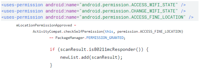
Figure.2 WiFi RTT API Initialization
First of all, ACCESS_FINE_LOCATION permission needs to be declared in the Manifest file. Then, there needs to be an if statement in the Main Activity file checking if the “PackageManager.PERMISSION_GRANTED” indicator is true or not. If it is true, this means that the device supports WiFi RTT API. Finally, there needs to be an if statement checking if the “scanResult.is80211mcResponder()” returns true or not. If it is true again, this means that the AP is WiFi RTT capable. System service “WIFI_RTT_RANGING_SERVICE” needs to be granted permission for using the WiFiRTTManager in Android. If all of the steps are completed without fail, the application is ready for development.
We used three hardware for our project, one device as a slave station to receive FTM, and two responder APs as a master FTM sender. Since we are testing the WiFi RTT on Android so that we chose Pixel phone since it has unaltered Android OS. We used a Pixel 2 phone with the latest Android P OS updated. Pixel 2 phone is based on a Qualcomm Snapdragon 835 SoC. The APs we chose to use is Google WiFi based on Qualcomm IPQ4019 and WILD device based on Intel 8260AC. Google WiFi has four antennas located around the device’s circumstance. The WILD AP has two RP-SMA antennas. In the real testing setups, Google WiFi and WILD AP have a similar range of around 25 meters with -80db, while the maximum possible working distance could reach over 100 meters in absolute free space.
Since in most of the test scenarios we don’t have power outlets available, we are using car 12V power supply to power the APs. We use 12V to 110V AC power adapter and extension cords to put the APs to our specified locations. The setup is shown in the figure below:
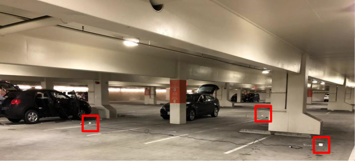
Figure.3 Localization setup
For localization purpose, we have two cars supply power for three Google WiFis as shown in the red box. An extension cord is used to power the third WiFi access point. Assume we are localizing within a Cartesian coordinate system, the three Google WiFi is located at (10,10), (15,20), (20,10) coordinates. The unit of measurements is in meter. For WILD localization, the coordinates for the two WILD devices is (10,0), (20,0). Due to the limitation of the number of WILD devices, we can only put the WILD device on the x-axis and localizing in the first quadrant. For both devices, we are placing the APs on the ground to ensure we are localizing in a 2-D plane (z = 0). We are also deliberately put the measuring device (Pixel 2) right on the ground to ensure it is in the same plane as the APs. In the application Findurcar, since the precision requirement is not strict for this application, we are neglecting the phone’s vertical distance above the ground while using the app. The characterization experiments are done in different environments setups for ranging precision and compared between the devices for localization precision. The test environments includes temperature variance tested in the same parking lot at noon and at night with low occupancy in the lots, parking lot occupancy variance tested in the same indoor parking lot at different time on workday, obstacle variance tested in in-room condition, antenna orientation variation tested at all eight orientations for both AP devices and finally a test conducted vertically in the parking lot penetrating concrete obstacle. The data collected in these experiments are shown in section V.
Localization algorithms we used for both scenarios will be discussed in section VI of this report.
Before I get into data analysis, I want to show how the data are collected and arranged. For every testing scenarios, we collected samples for that are equally spaced and this information was presented on the x-axis of the graphs. For each recorded set, there were 10 values recorded. The distance difference was calculated by taking the median of the 10 values and subtracting it to the true value measured by a tape measure. The y-axis of the graphs represents the difference from the true value. For detailed information about the data, please look at the data spreadsheet.
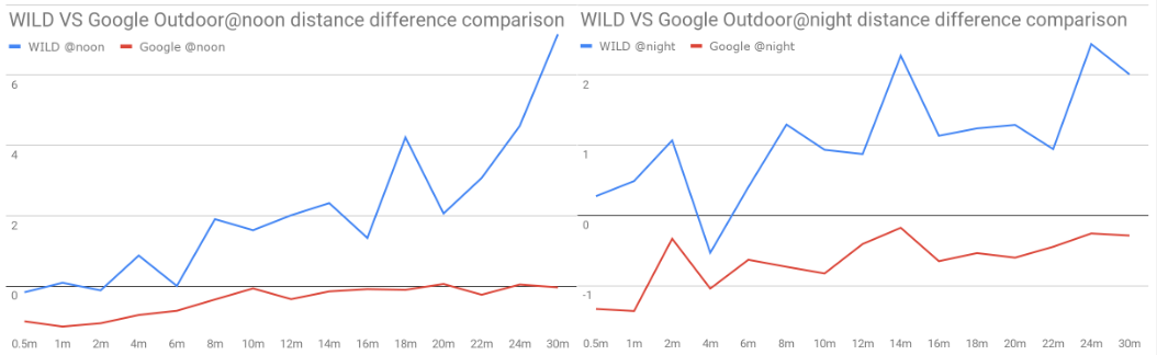
Figure.4 WILD VS Google temperature
The noon temperature was 17.5℃ (63.5℉) and the night was 9℃ (48.2℉). We can see that Google AP performed better than WILD as it was generally closer to the x-axis meaning it was closer to the true value.
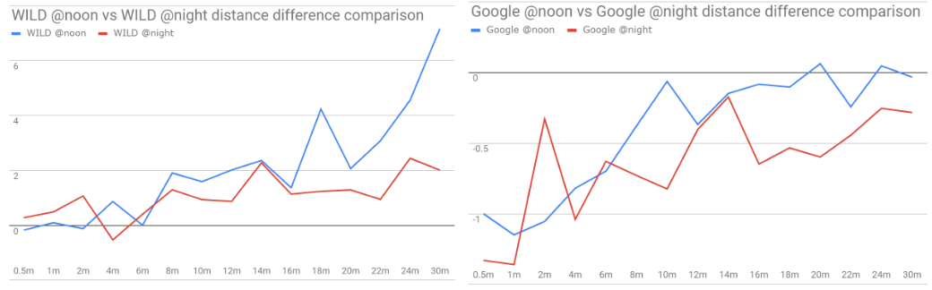
Figure.5 Noon VS Night
WILD and Google APs were compared to themselves and the results showed that WILD at night is better than noon but Google at noon is better than at night. Still, Google APs were closer to the x-axis than the WILD APs.
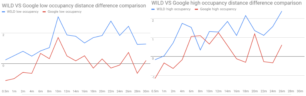
Figure.6 WILD VS Google occupancy
High and low occupancy meant the number of cars and the crowdedness of the traffic in a parking lot. We chose the midday and midnight of a parking lot to represent occupancy. Google APs were better than WILD AP although the difference was smaller compared to previous comparisons.
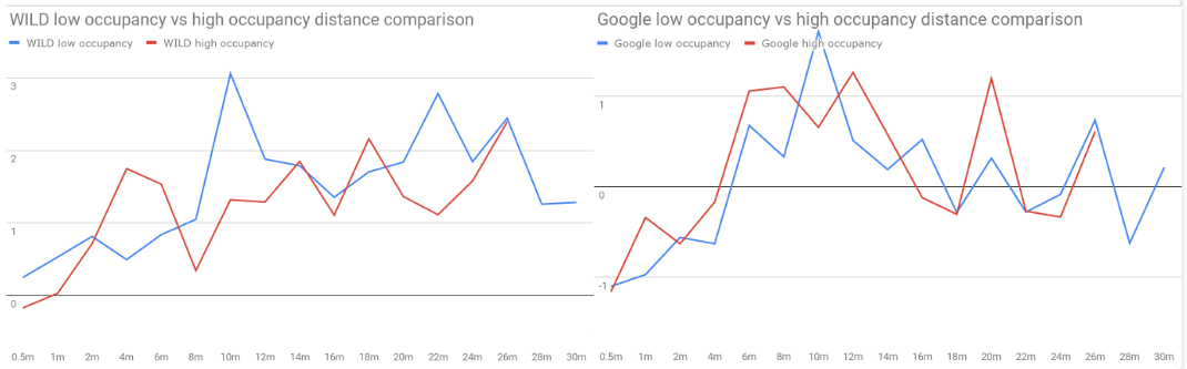
Figure.7 High VS Low occupancy
Both WILD and Google APs performed similarly with WILD had a slightly higher distance difference. Here, it is clear to say that high occupancy does not affect the distance accuracy but it indeed affects the measurement of the distance range as there are no 28m and 30m measurement available in high occupancy case.
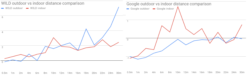
Figure.8 Outdoor VS Indoor
WILD APs performed better in indoor situations while Google APs performed better in outdoor situations. Overall, Google APs still performed better than WILD APs.
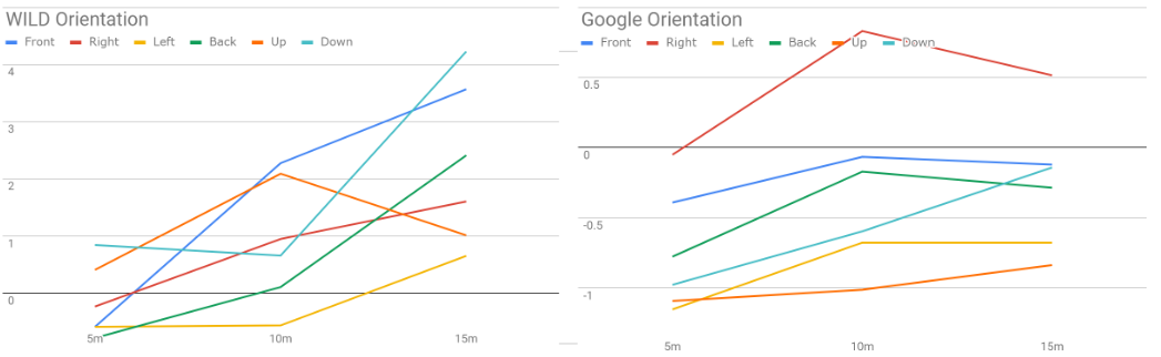
Figure.9 WILD VS Google Orientation
By fixing the position of the APs on the ground and changing the location of the pixel phone, the orientation data was measured. We can see that Google APs performed consistently in all orientations and it performed better than the WILD APs. The reason can be the number of antennas and position angles on both APs. Google AP has 4 antennas placed around the device whereas WILD APs had 2 antennas facing the same direction, not covering as many angles compared to Google AP.
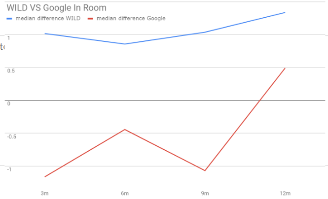
Figure.10 WILD VS Google inroom
Both APs performed similarly to each other. Now, it is clear to say that Google APs has a small offset at lower distances making the distance difference at small values always negative. We believed Google API was calibrated using the Google AP and adding an offset made the Google AP more accurate than the WILD AP.
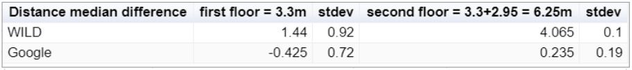
Figure.11 WILD VS Google obstacles
The ability to penetrate obstacles was one of the characters compared. Two APs were placed on the first floor of a parking lot and distances were estimated on the second and third floor of the parking lot. It is clear to see from the table that both distance difference and standard deviation of Google AP is better than the WILD AP.
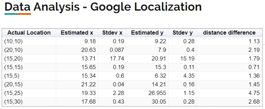
Figure.12 Google Localization
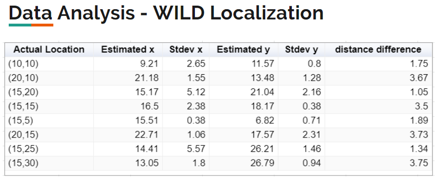
Figure.13 WILD Localization
In the location comparison, Google APs had an average distance difference of 1.85m and WILD APs had an average distance difference of 2.58m. It is also clear to see that Google APs estimated accurate distance more consistently than WILD APs.
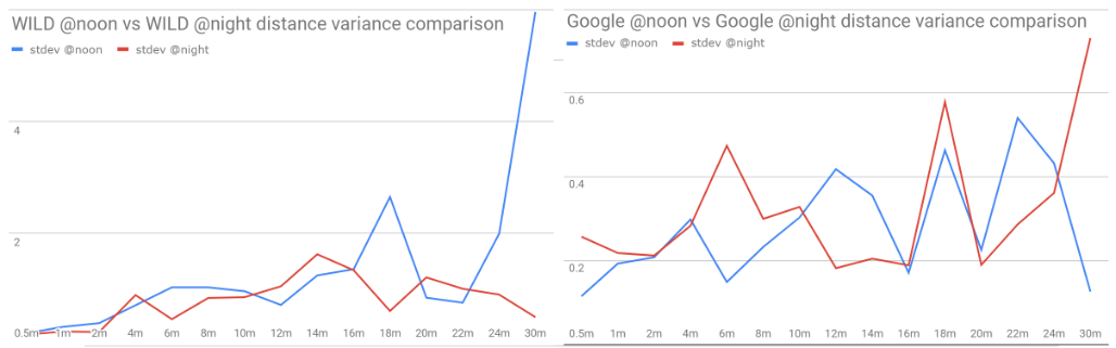
Figure.14 WILD VS Google distance standard deviation
Comparing the distance difference standard deviation between Google AP and WILD AP, the fluctuation at night is much smaller than noon for WILD. Google AP performed steady and overall better than WILD looking at the y-axis.
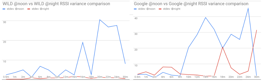
Figure.15 WILD VS Google RSSI standard deviation
Comparing the RSSI difference standard deviation, the standard deviation at night for WILD AP performed better than all the other three curves. From the previous comparisons, we can see that Google AP estimated more accurately than WILD AP, so this means that the RSSI measurement may not be proportional to the distance estimated. RSSI can be affected by a lot of factors, like heavy traffic or high-frequency noise, so it is not a good method to estimate distance comparing to the time of flight method using by Google API.
Finally, Here are some key takeaway points: WILD APs are accurate at shorter distance(<2m) and inaccurate as the distance increases. Google has small offset at small distances making it not accurate than WILD but becomes accurate at longer distances. High occupancy affects the range of measurement, not the distance estimation. Google API’s RTT method performs better than the RSSI method in the parking lot. In a scenario of finding a car in a parking lot, Google AP works better than WILD AP.
i) Motivation In many large scale parking lots like the ones underground large stores like IKEA, many people are having trouble finding their parked cars. In such large closed parking structures, usually GPS signal could not penetrate so that the location is hard to be determined only using GPS. Some large malls like Westfield have come up with solutions to install a camera over each of the parking spots and use image processing to recognize the license plates of the parked cars and provide spot information for customers. While this kind of solutions need a huge budget for installing a huge amount of cameras and cannot provide real-time directions for users to find their cars. The WiFi RTT provided a perfect tool for localization for these indoor situations with minimum changes to the parking lot and provide the user with real-time direction information. In our proof-of-concept design, we only require the users’ phones within the range of three WiFi AP to provide information about the relative location of them and their cars. The application could be extendable into more complex situations.
ii) App UI Since we designed and used this app for both characterization experiment data collecting and proof of concept for the car finding application, the UI is more complicated and coarse than the commercialized apps. The initial UI is shown in the figure below.
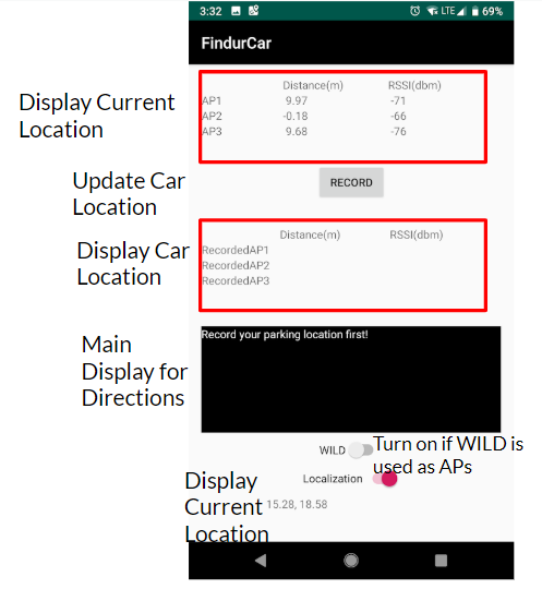
Figure.16 Findurcar application UI
The current distance measurements from the APs are displayed in the first red box, and the record button enables the user to record the current measurement into the second red box for future reference of parked car location. The black area is the main display for Findurcar directions. Once the car location is located and the current location is determined, the direction would show your parked car’s orientation and distance from your current location. For example, if your parked car is 10 meters away on your right, the direction will show “Your car is 10 meters away on your right.” If your car is within 3 meters away from you, it will display “Found your car!”. The two switches below the main display are only for the project use. The “WILD” switch is used for switching from Google AP mode to WILD mode. The app will only recognize one kind of AP since we hardcoded the AP’s MAC address. For reusing our app, the MAC address needs to be changed according to the APs. The last switch is for switching localization on. Since the locations of APs are also hardcoded into the app, only the specified AP is accurately placed on a specified location, the localization gives accurate results. For reusing our app, the hardcoded coordinates of our APs would also need to be changed.
iii) User Manual The app used WiFi RTT as the tool to tell the distance between the user and the parked car, and ROTATION_VECTOR sensor as the tool to tell the orientation of the parked car corresponding to the user’s current orientation. As the user walks or turns, both distance and orientation displayed will be updated according to the user’s real-time location and orientation. The demo could be found at https://youtu.be/3Qu_qaIWJbA. Since we are using magnetometer as the main sensor for orientation detection, the user will need to hold the phone normally (not parallel to the ground) and keep it stable to get accurate reading and directions.
To use the app, the user needs to record the car’s location when the car is parked in the spot by clicking the record button. Then, when they came back into the WiFi range and could not find the car, they could see the direction automatically displayed in the main display as long as the app is opened. The only operation the user needs to do is to record the car’s location. Also, further improvement for the app could be done to record the location automatically, which is similar to Google Maps’ auto record function.
iv) Localization Algorithm
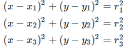
Figure.17 3-point localization
The localization algorithm constructs equations in a 2D coordinate system knowing the APs positions and recorded distance from our app. As we have 3 Google APs and 2 WILD APs, we will have 3 equations for Google and 2 for WILD. In the Google AP case, from each pair of equations in the 3 equations, we are able to get an equation of a line. This line consists of all points that satisfy this pair of equations. For every two lines, we can calculate the intersect point. Finally, we are left with 3 points and we take the centroid of the three points. This is our estimated location. In the WILD case, we only have two APs for testing, so we put the two APs at the x-axis of the 2D coordinate system. This means that we can eliminate one of the 2nd order terms in the 2 equations. We can solve the equation and get two location points and we pick the one in the first quadrant.
v) Orientation Algorithm
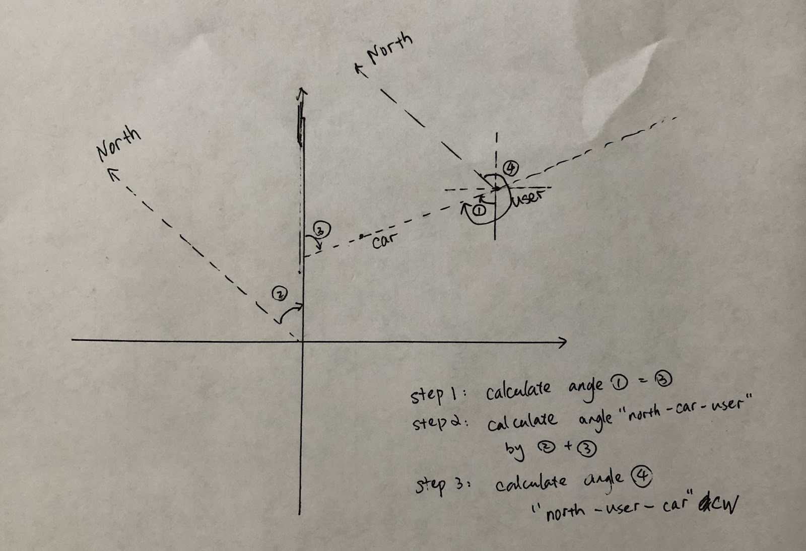
Figure.18 Orientation algorithm
The orientation algorithm aims to update the user orientation and distance information so it is easier to walk to that location. We use the IMU sensor in the pixel phone to get the rotation vector information of the pixel phone. The orientation that the sensor returns is based on the angle between the North pole and the phone pointing direction clockwise. We need to record the angle between the North pole to the y-axis in the 2D coordinate system. Looking at the image, angel 1 and 3 can be easily calculated using two coordinate of the car and user location. Angle 2 is known from the orientation of the y-axis. The addition of angle 2 and 3 gives angle 4 and we can add 180 degrees to angle 4 and get the angle between the North pole and the car. This angle subtracts the rotation angle given by the pixel phone will result in the angle from the user to the car. This angle is finally characterized into 8 directions. (Front, Front-Left, Left, Rear-Left, Rear, Rear-Right, Right, Front-Right) Notice that this algorithm will be different based on the position of the user and the car, so for details of the algorithm, please review the Android application Main Activity file.
Future work can be divided into two parts. The first part is theory and the other part is our Findurcar application. Theory In this project, we are using 3 Google APs and 2 WILD APs but in reality, we need much more APs to cover larger areas. Therefore, new algorithms need to be developed to satisfy switching APs and optimizing the location precision using more than 3 APs. We neglect height as a factor of location in this project as all of the equations involve only two dimensions. In reality, there will be a height difference between the phone and the AP, so there needs to be a new algorithm developed to accommodate this change. The Findurcar application We can improve the UI to add more features to the application like auto-record the location when detecting the car is already stopped. In this project, we prerecord the location information of the parking lot that we will test. In reality, we can fuse a map in the application and use GPS signal to locate the parking lot that we are in. Then the application can switch to the interior map of the parking lot and the user location can be pinpointed on the map with direction to the car.
The characterization result for the WiFi Round-Trip-Time measurement is very desirable. We found both WILD and Google devices can achieve high accuracy in various environment setups. Even if the RSSI is low and the signal becomes weak, the distance measurement is still accurate enough for most of the applications. Google AP has higher accuracy in longer distance and WILD AP has higher accuracy in shorter distance relatively. Although we are using a coarse algorithm for estimating location, the localization result for both devices is around 2 meters. After testing the Findurcar application we developed, we found that the direction displayed in the app is accurate and working. Using the directions displayed in the app, we can find our recorded car faultlessly. It is very likely that WiFi RTT could be developed to be used in different indoor localization applications.
[2] https://www.gpsworld.com/how-to-achieve-1-meter-accuracy-in-android/
[3] M. Ibrahim, et. al, Verification: Accuracy Evaluation of WiFi Fine Time Measurements on an Open Platform, MobiCom’ 18, New Delhi, India