Temperature dependent fan control with Web Interface.
The aim of this project is to control a cooling system (in this case a fan) by using a temperature sensor. In addition, the system can be switched on or off via a Web Interface. To realize this project, the following things are used in this system:
- Arduino Mega 2560
- ESP8266-ESP1
- DHT11 Sensor
- a Fan
- V9 Batterie
- Relay Module (here it's a HL-54S v1.0)
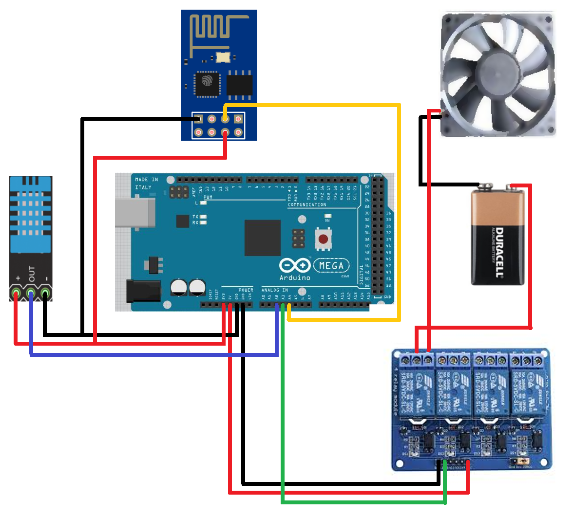
The Arduino is the centerpiece, which provides most of the code and is wired to the remaining parts. The ESP is a module that integrates a small microcontroller with a 802-11 Wifi Transmitter. This module contains the remaining code and is the Web Interface for this system. The temperature is measured via the DHT11 sensor. If the temperature is too high, the relay is switched, which in return closes the circuit between the battery and the fan. The relay can also be connected to multiple circuits. In this project only one fan is used to keep it simple. The system can be scaled to any size.
The ESP is the only part of this system that needs to be programmed but does not have an USB interface. To program the ESP module one needs an operating system. The NodeMCU is an open source platform and includes a firmware which runs on the ESP module.
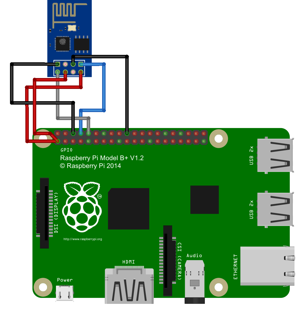
One way to flash the NodeMCU firmware on the module is by using a Raspberry Pi. To update the firmware, a tool called ESPTool is needed. The pyhton program does the update based on a binary file. Before downloading the ESPtool, the Python serial library must be installed using the command:
pi@raspberrypi ~ $ sudo apt-get install python-serial
Download and unpack the folder. The next step is to download the image of the updated NodeMCU, which can be found on github. The binary has to be in the ESPtool-master folder. Now comes the wiring between the ESP module and the Raspberry Pi.
| Raspberry Pi | ESP | Comment |
|---|---|---|
| 01; 3.3v | VCC | direct current |
| 01; 3.3v | enable | responsible for enabling the operation of the transmitter |
| 06; ground | GND | ground |
| 08; TX | RX | transmitter to receiver |
| 10; RX | TX | receiver to transmitter |
| 20; ground | gpio0 | has to be pulled low to get into flash mode |
After the ESP is wired with the Raspberry Pi, everything is ready to flash the firmware. Now run the terminal by using the following command:
pi@raspberrypi ~ $ sudo python esptool.py --port /dev/ttyAMA0 write_flash 0x00000 nodemcu-master-7-modules-2018-03-27-13-49-36-float.bin
If it has successfully passed, the result will be identical to the console above. The next step is to disconnect the cable VCC pin module and also disconnect the cable that connects the GPIO0 to the GND, then reconnect the VCC cable to the module.
Another tool for the ESP is the ESPlorer. ESPlorer is an IDE for developing on the ESP. Via the ESPlorer, Lua files can be written and uploaded to the ESP. Open the port and the ESPlorer will display the firmware specifications. If the ESP gets turned on, the firmeware will look for the init.lua file and will execute this file.
function checkWiFiStatus()
	local s = wifi.sta.status()
	print("WiFi Status: " .. s)
	if s == 5 then
		tmr.stop(0)
		print("Connected on " .. wifi.sta.getip())
		print("Testoutput Check WIFI")
		dofile("runWebServer.lua")
	end
end

wifi.setmode(wifi.STATION)
station_cfg={}
station_cfg.ssid="WiFiSSID"
station_cfg.pwd="password"
wifi.sta.config(station_cfg)
print('Verbindungsversuch')
wifi.sta.connect()
tmr.alarm(0, 1000, 1, checkWiFiStatus)
This script tries to connect to a WiFi with the specified SSID and password. If the connection was successful, the next file (runWebServer.lua) will be executed.
print("Webserver starts")
gpio.mode(4, gpio.OUTPUT)
gpio.write(4, gpio.LOW)
print("WIFI Status before Server start, WIFI Status "..wifi.sta.status())
srv=net.createServer(net.TCP, 3)

print("Server created on " .. wifi.sta.getip())

srv:listen(80,function(conn)
	conn:on("receive",function(conn,request)
		print(request)
		_, j = string.find(request, 'control_switch=')
		if j ~= nil then
			command = string.sub(request, j + 1)
			if command == 'on' then
				gpio.write(4, gpio.HIGH)
                	else
				gpio.write(4, gpio.LOW)
			end
		end
		conn:send('<!DOCTYPE html>')
		conn:send('<html lang="en">')
		conn:send('<head><meta charset="utf-8" />')
		conn:send('<title>ESP Server</title></head>')
		conn:send('<body><h1>Fan Control Web Interface</h1>')
		-- Send the current status of the Fan Control unit
		if gpio.read(4) == gpio.HIGH then
			fan = "ON"
		else
			fan = "OFF"
		end
		conn:send('<p> Status of the fan unit : ' .. fan .. '</p>')
		conn:send('<form method="post">')
		conn:send('<input type="radio" name="control_switch" value="on">ON</input><br />')
		conn:send('<input type="radio" name="control_switch" value="off">OFF</input><br />')
		conn:send('<input type="submit" value="Fan Control Switch" />')
		conn:send('</form></body></html>')
	end)
end)
In the runWebServer script, the module starts a Web Server. It contains a little interface in which the power controll of the fan can be turned on or off. This function is realized by a pin. The gpio0 pin from the ESP is connected to the Arduino board. If the pin is low, the fan is turned off. If the pin is high, then the fan will be turned on regardless of the temperature coming from the DHT11. After uploading both scripts to the ESP, the ESP can be unplugged from the Raspberry Pi.
This is the total wiring. Everything is connected with the arduino, except the fan and the battery. The DHT11 sensor sends its temperature data to the Arduino board. If the temperature is above 30°C, then the relay is switched and the 2nd circuit with the battery and the fan closes. When the temperature drops below 25°C again, the relay will switch back and the circuit is no longer closed. The DHT11 sensor and the ESP module require a 3.3V voltage while the relay needs a 5V voltage.
#include <Adafruit_Sensor.h>
#include <DHT.h>
#include <DHT_U.h>

#define DHTPIN            2         // Pin which is connected to the DHT sensor.
#define RELAYPIN 3
#define ESPPIN 4

// Uncomment the type of sensor in use:
#define DHTTYPE           DHT11     // DHT 11

DHT_Unified dht(DHTPIN, DHTTYPE);

uint32_t delayMS;

uint32_t upperLimit = 30;
uint32_t lowerlimit = 25;
bool powerStatus = false;

void setup() {
  Serial.begin(9600);
  // Initialize device.
  dht.begin();
  // Print temperature sensor details.
  sensor_t sensor;
  dht.temperature().getSensor(&sensor);
  Serial.println("------------------------------------");
  Serial.println("Temperature");
  Serial.print  ("Sensor:       "); Serial.println(sensor.name);
  Serial.print  ("Driver Ver:   "); Serial.println(sensor.version);
  Serial.print  ("Unique ID:    "); Serial.println(sensor.sensor_id);
  Serial.print  ("Max Value:    "); Serial.print(sensor.max_value); Serial.println(" *C");
  Serial.print  ("Min Value:    "); Serial.print(sensor.min_value); Serial.println(" *C");
  Serial.print  ("Resolution:   "); Serial.print(sensor.resolution); Serial.println(" *C");
  Serial.println("------------------------------------");
  // Set delay between sensor readings based on sensor details.
  delayMS = sensor.min_delay / 1000;

  // Initilize relay Output
  pinMode(RELAYPIN, OUTPUT);
  digitalWrite(RELAYPIN, HIGH);

  // Initilize ESP INPUT
  pinMode(ESPPIN, INPUT);
}

void loop() {
  // Delay between measurements.
  delay(delayMS);
  // Get temperature event and print its value.
  sensors_event_t event;
  dht.temperature().getEvent(&event);
  if (isnan(event.temperature)) {
    Serial.println("Error reading temperature!");
  }
  else {
    uint32_t temperature = event.temperature;
    Serial.print("Temperature: ");
    Serial.print(temperature);
    Serial.println(" *C");

    if(temperature < lowerlimit){
      powerStatus = false;
    } else if(temperature > upperLimit){
      powerStatus = true;
    }
  }

  // turn Relay on when dht11 Temperature is higher then 25
  if(powerStatus && digitalRead(ESPPIN) == HIGH){
    // relay Pin has to be low if relay has to switch electrical ports
    digitalWrite(RELAYPIN, LOW);
  } else {
    digitalWrite(RELAYPIN, HIGH);
  }
}The project dealt with a cooling system controlled by a temperature sensor and a web interface. The system can be further built with multiple temperature sensors and/or multiple fans or another cooling system.

