Writing Firmware to the ERF stick
Set up cc-tool on a Linux machine (eg: Raspberry Pi)
Alternatively, use Windows with these TI tools. The V1 Flash Programmer is what is required.
The most fiddly part of the process is connecting the TI CC-Debugger to the ERF stick.
- http://paulswasteland.blogspot.co.uk/2015/01/building-your-own-firmware-for-ciseco.html shows the correct pin mapping
- http://web.archive.org/web/20150825032001/http://openmicros.org/index.php/articles/88-ciseco-product-documentation/259-srf-technical-data shows the pinout for the SRF part of the ERF board
I've taken some photos showing connections from the CC-debugger cable through to the ERF stick. Unfortunately I've had to mix the colours a bit as I don't have connectors of matching colours - sorry!
If in doubt, go back to the diagrams referred to above.
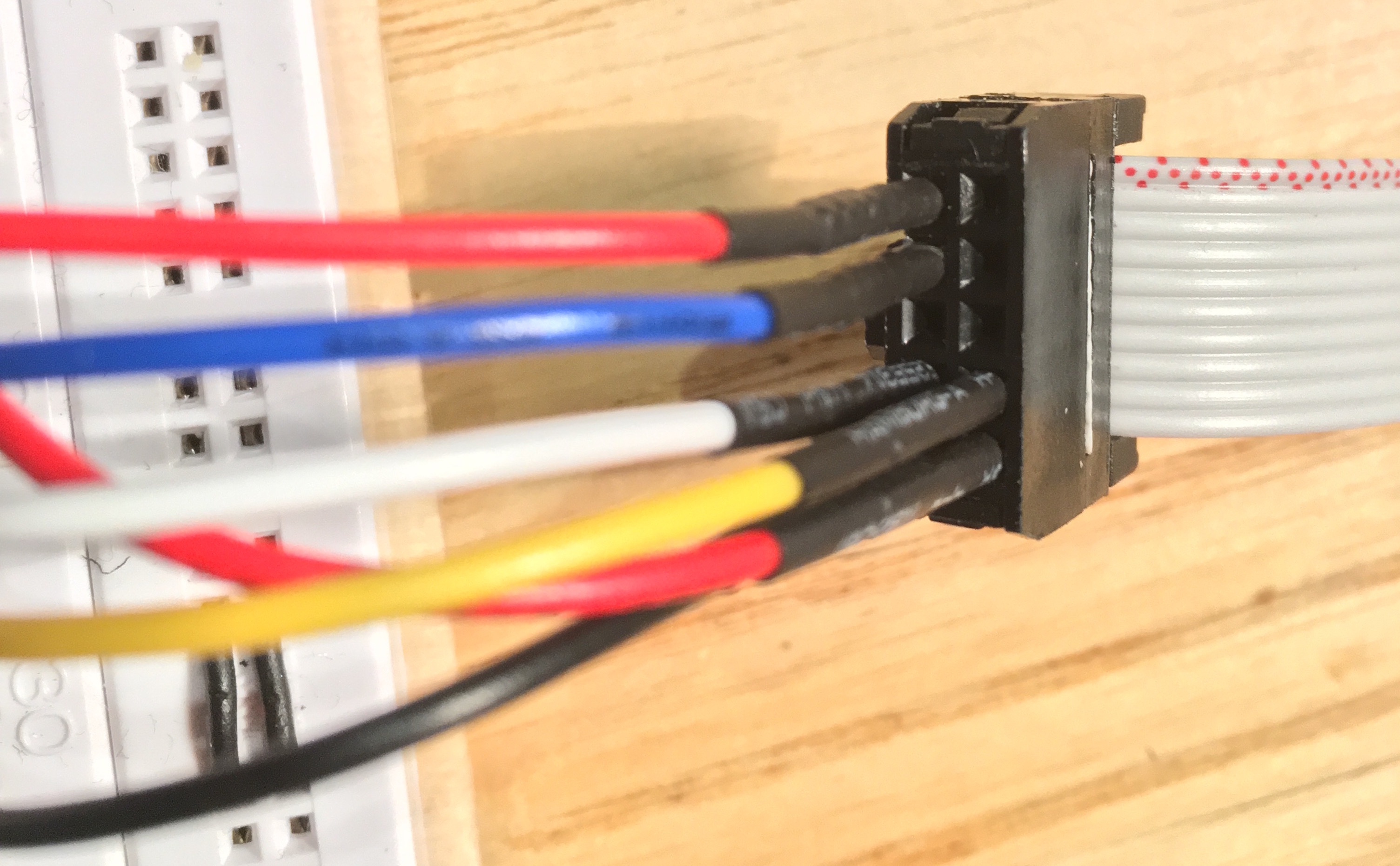
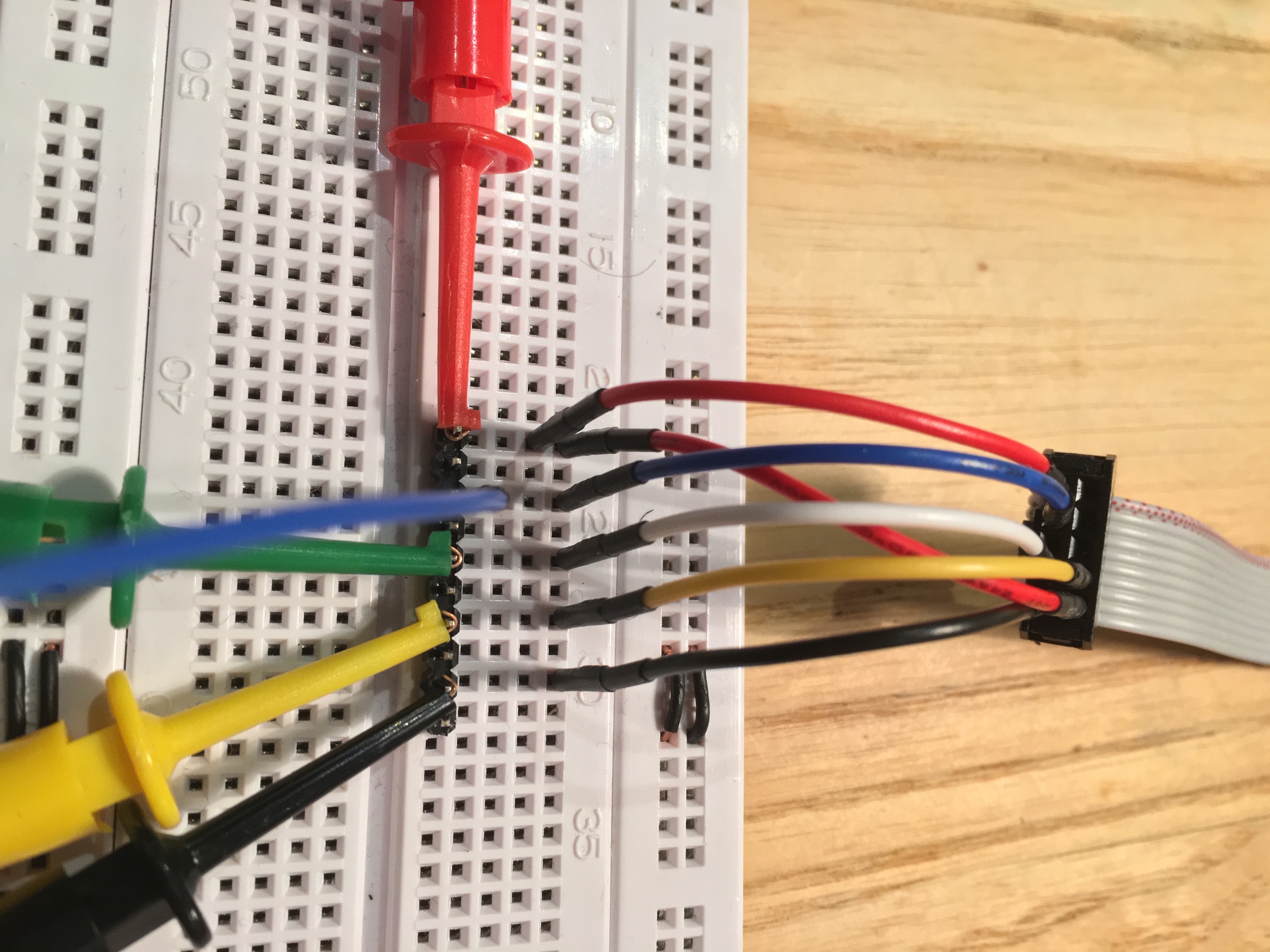
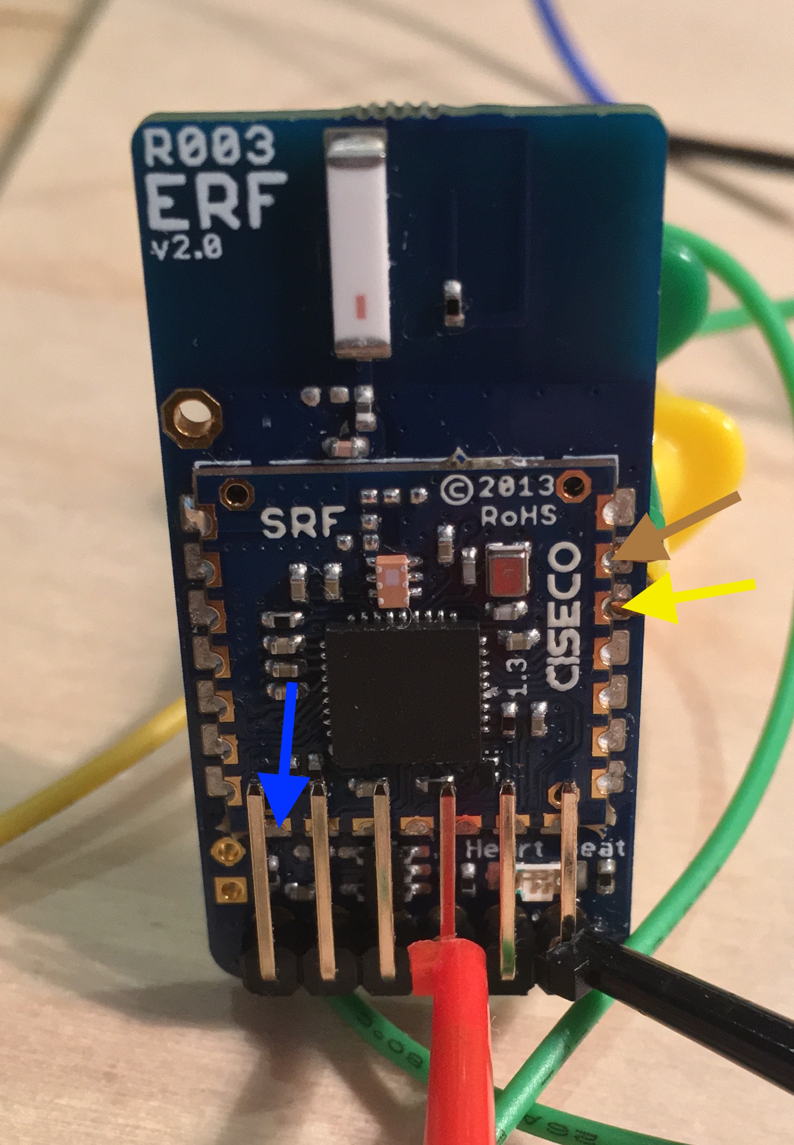
The power (red for +ve and black for -ve) go onto the built-in-pins. However, the green, yellow, and blue connect to the pins of the SRF module that's been soldered onto the ERF stick at production time.
Note that the 'blue' connection (reset) isn't shown in the last picture as I had to hold it by hand and couldn't take a photo and hold it in place at the same time. Blue goes onto the first-pin along the bottom of the SRF module that's soldered onto the ERF stick. Like the green and yellow, it connects not onto the built-in pins, but
Once everything above is connected, in the subg_rfcat directory run the following command:
make -f Makefile.uart0_alt1 BOARD_TYPE=SRF_ERF install
This should then write the firmware to the board.
Connect the ERF's TX, RX, PWR and GND ports to a serial device and then run the following in the subg_rfspy directory:
subg_rfspy$ RFSPY_RTSCTS=0 ./tools/get_rfspy_version.py /dev/ttyMFD1
You should get output something like this if everything's ok:
    Version: subg_rfspy 0.3
    Response: subg_rfspy 0.3