Add PIO SPI slave example #115
Comments
|
Yeah, I have looked at that. The problem is that solution only works for master mode, and I need this functionality for slave mode. As far as I can tell the only fix would be to reimplement SPI as a PIO state machine, however I'm pretty new to this stuff so I could be wrong. |
|
I'm not very familiar with SPI code (and so there may be a better workaround than what I'm suggesting), but would changing your |
I have tried something similar to what you are suggesting. I looked into how the spi.c file and saw that the |
|
It actually seems like something similar to what I was thinking of is actually already implemented in the clocked_input.pio example. I'll give it a try and see if this works as a solution to my issue. |
|
Good news, the clocked input pio example actually works as-is, as it completely ignores the CS line all together. However, I would like to request an actual SPI implementation rather than just reading in data on a clock signal. |
|
See also #104 |
This is how one variant of SPI functions. Unfortunately the PL022 doesn't support this variant in slave mode. To do this with PIO, you could try something like the following (just a sketch, not promising there are no typos): This uses the |
|
Hello, I know issue was indicated closed - but I was curious and did a deeper dive into the reason for SPI issue receiving only first byte in slave mode. The reason can be found on page 535 of current RP2040 Datasheet.
Solution for now would be to use interrupt on chip select (which was suggested before) to enable and disable internal SPI accordingly. The RP2040 datasheet details how this is done - not positive of support in Pico SDK. Plan to look further in coming week. Wonder though, is there a PIO state machine that can do same with internal SPI hardware making the chip select operate more like we are all expecting where chip select is held? I still have lots to learn about PIO. |
|
Another comment for this closed thread, MikeLoh is absolutely right that this is mentioned in the datasheet, but one quick note on that, the RP2040 behavior is different depending on the SPI phase. His quote above is for SPH=0, while below is the datasheet comment for SPH=1.
I've tested this myself, and indeed if you operate the SPI with CPHA=1 (CPOL doesn't matter for this), the SPI slave will operate correctly in the "standard" way and will receive all bytes with CS staying low for the duration of the transfer. It's very odd to me that changing the SPI phase would have this effect, but it might be a usable workaround for some people. |
|
@suicidaleggroll I had discovered this same workaround and also have successfully tested. Fortunately it will work with our implementation to have SPH=0, giving us the operation we expect. Sorry, had not gotten around to posting this update to here. |
I currently have an Arduino Mega in SPI master mode, and a RPi Pico in slave mode, communicating over SPI. I was using the mega to troubleshoot some issues I was having.
My pinout is:
Here is the Pico's code:
and here is the Arduino's code:
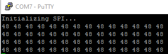
This code sends the byte array buffer over SPI, setting CS to LOW, completing the transfer, then setting CS back to HIGH, as this is how the SPI protocol is supposed to function. However, in doing so, the Pico only receives the first byte of each transfer, waiting until it recieves 14 bytes and then displaying all the first byte.
Pico serial output:
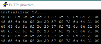
After doing some fiddling around with the code, I realized that if I change the loop to toggle CS on each byte sent, the Pico successfully receives all of the data.
New Pico serial output:
However, this is not how the SPI protocol should operate and makes the Pico incompatible with pretty much every SPI master device, and seems to be an issue in the pico's hardware_spi library, unless this is user error and if that is the case then I will gladly be corrected.
The text was updated successfully, but these errors were encountered: