-
Notifications
You must be signed in to change notification settings - Fork 1.6k
Connecting Grbl
This wiki is intended to provide various instructions on how to connect to grbl in various ways. Please feel free to contribute more up-to-date or alternative methods.
For Grbl v0.9 and v1.1+ default builds: (NOTE: Z-limit is on D12 and the spindle enable pin uses the hardware PWM on D11.)

For Grbl v0.8 and v0.9+ with variable spindle disabled, Z-limit moves to D11 and spindle enable to D12. This is generally for backward compatibility on older boards.
For Laser mode, the pin used is the same as Spindle (PIN 11).
First, to connect your stepper motors to Grbl, you'll need some stepper motor drivers to power the steppers and connect your driver inputs to the Arduino controller pins. There are a number of drivers that can do this, available as fully pre-built, partially pre-built, or completely DIY. There are some examples farther down the page. The stepper drivers will need to share the stepper enable pin (D8) to their respective enable pins, while the direction and step pulse pins (D2-D7) will need to be connected to their respective pins on the drivers. Just make sure that all of your drivers and the Arduino share a common ground (star grounded with your motor driver power). This is about all you'll need to get started.
Afterwards, once you decide that you're ready or would like to enable homing and/or hard limits, you'll need to connect a normally-open limit switch to each of the limit pins (D9, D10, and D12). Homing and hard limits use the same switches. These limit pins are already held high with an internal pull-up resistor, so all you have to do is wire them to ground. So when you close a switch, the switch will pull the limit pin to ground. If you'd like to have hard limit switches on both ends of travel of an axis, just wire two limit switches in parallel to the axis limit pin and ground. Make sure you have the switches installed before attempting to perform a homing cycle, and make sure you practice good wiring methods to minimize external electric noise on the input pins.
In Grbl v0.8 and later, there are pin-outs of the cycle start, feed hold, and reset runtime commands, so you can have physical control buttons on your machine. Just like the limit pins, these pins are held high with an internal pull-up resistor, so all you have to do is connect a normally-open switch to each pin and to ground. Again make sure you practice good wiring methods to minimize external electric noise on the input pins.
If you have a desire or need for spindle or coolant control, Grbl will toggle these output pins (D13, A3) high or low, depending on the G-code commands you send to Grbl. With v0.9+ and variable spindle PWM enabled, the D11 pin will output a range of voltages from 0V to 5V depending the spindle speed G-code command. 0V indicates spindle off in this case. Since these pins are all application dependent in how they are used, we'll leave it to you to determine how to control and use these for your machine. You can also hack the spindle and coolant control source files to easily alter how they work and then compile and upload your modified Grbl through the Arduino IDE.
Last Updated: 2012-01-29 by Atrixium.
This is a fairly straightforward interface for a 3 axis machine.
The 'step signal ground' for each EasyDriver is connected together and tied to the GND pin of the Arduino. Do not confuse this with the motor ground or any other ground connection on the EasyDriver!
The 'Step' pin for the X,Y and Z axes is attached to digital pins 2, 3 and 4 respectively.
The 'Dir' pin for the X,Y and Z axes is attached to digital pins 5, 6 and 7 respectively.
Last Updated: 2012-02-21 by aldenhart.
grblshield - plugs on to Arduino for 3 axes of motor control - up to 2.5 amps per winding. Drivers are thermally protected against overcurrent and are therefore extremely resistant to burnout or failure.
Last Updated: 2012-02-03 by edwardrford.
buildlog.net arduino stepper shield - pololu driver carrier arduino shield for 3 axes of motor control. Replaceable drivers in case of damage.

Last Updated: 2016-06-10 by Protoneer.
Arduino CNC Shield - 3 independent axes and one clone axis.Uses Pololu Stepper Drivers with all GRBL pins exposed. GRBL 0.9 Compatible. RC filters on end stops and Probe pins.
Raspberry Pi CNC board/hat - 3 independent axes + 1 clonable drive and with removable screw terminals.Uses Pololu Stepper Drivers with all GRBL pins exposed. GRBL 0.9 Compatible. RC filters on end stops and Probe pins.
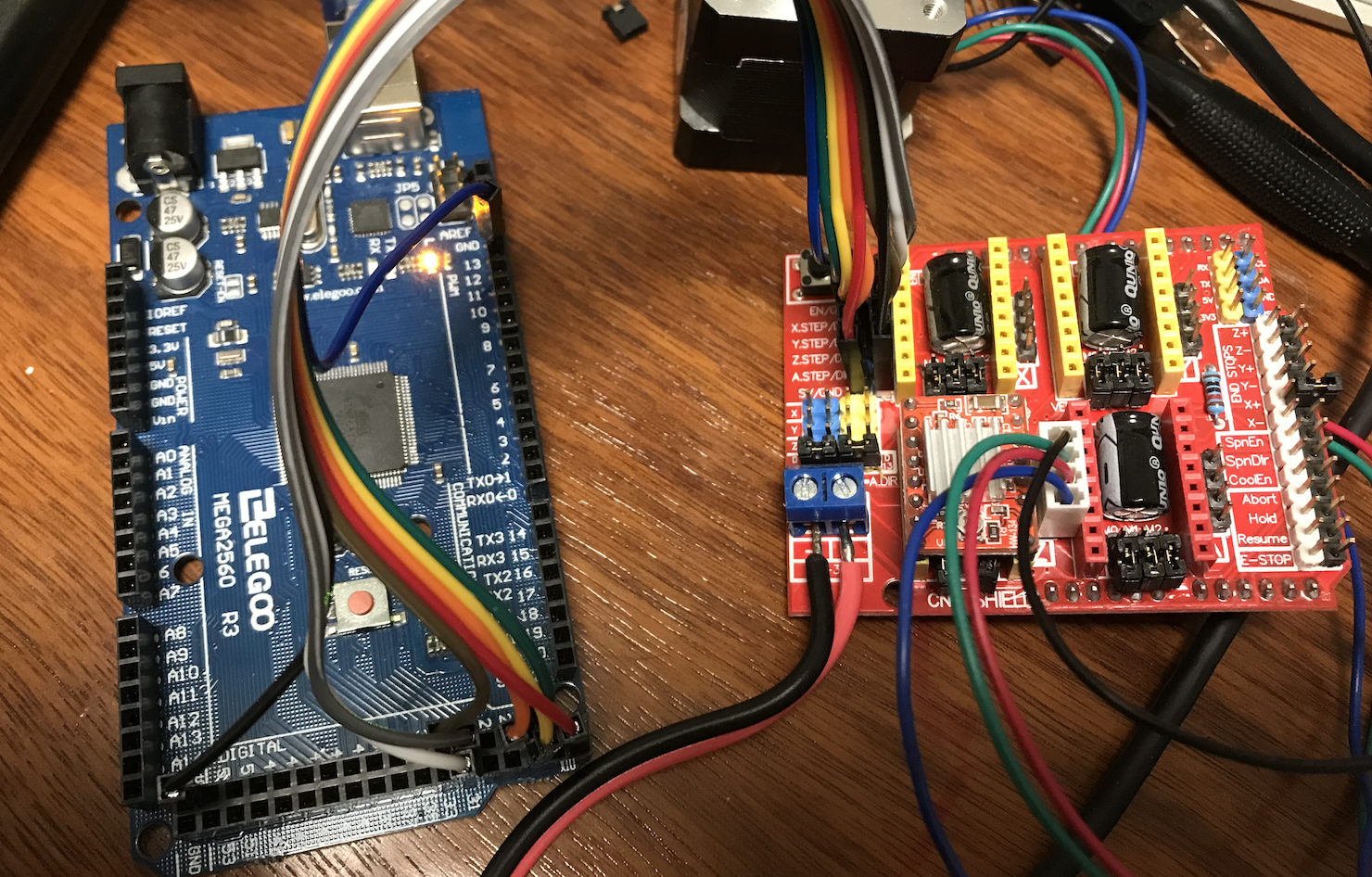
The Protoneer CNC Shield V3 does not connect as neatly to an Arduino Mega with grbl-Mega, (see https://github.com/gnea/grbl-Mega/issues/107#issuecomment-1066039958) but it is possible to use the 2-row header to connect to the Mega:

Some early work on supporting this can be found here. It is out-dated and uses Grbl v0.7.

