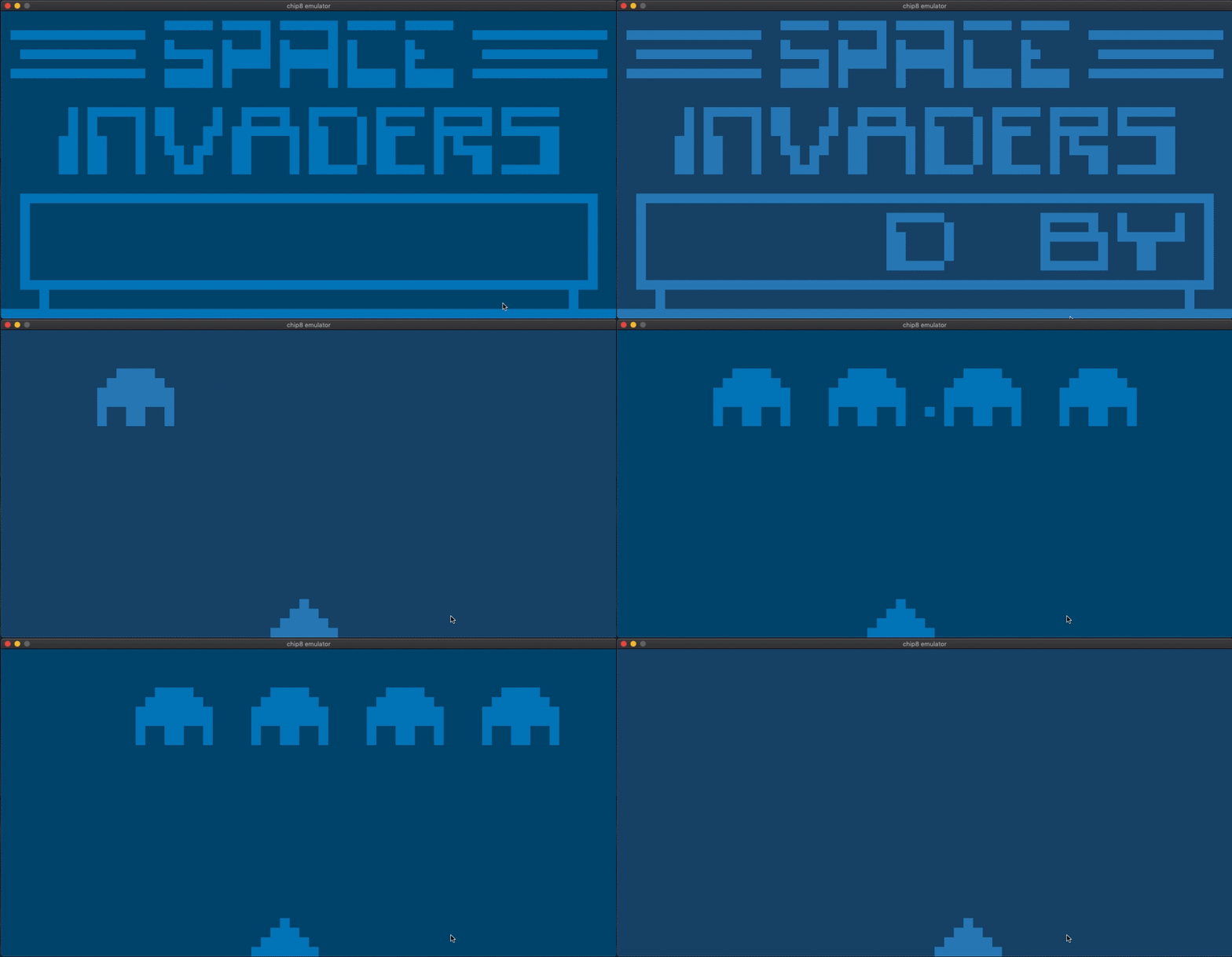
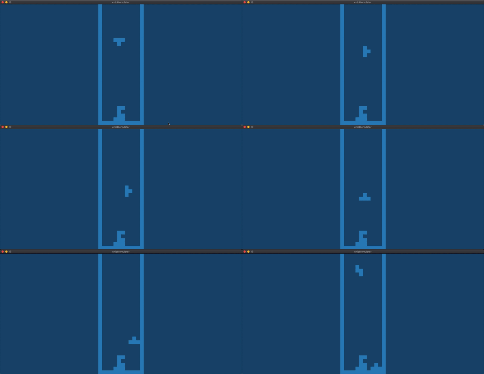
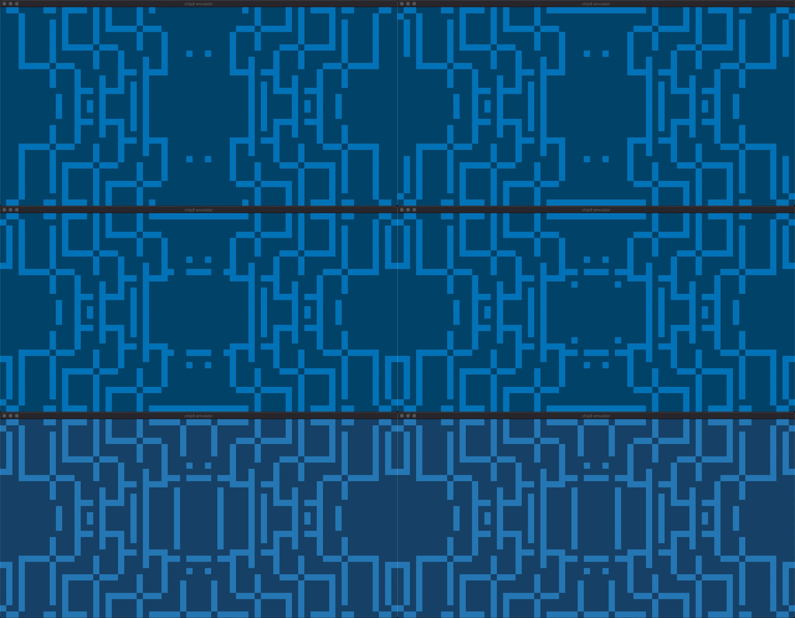
A Chip-8 emulator written in Rust. This is a rewrite of one of my previous projects, a Chip-8 emulator written in typed Racket. Choice of language aside, the differences between these emulators lie in their design and their overall quality. This emulator is smoother, more configurable, and far better at handling keyboard input. It also includes unit tests.
The auto-generated cargo docs can be found at https://wangtheo.github.io/chip8-rust/chip8/index.html
- Rust 2018 and Cargo - see https://www.rust-lang.org/tools/install for instructions
- SDL2 (for graphics and keyboard input) - see https://github.com/Rust-SDL2/rust-sdl2 for instructions
Clone this repo:
git clone https://github.com/wangtheo/chip8-rust.git
cd chip8-rust
Emulate a Chip-8 program:
cargo run <PATH TO CHIP8 PROGRAM>
Example Chip-8 programs may be found in the roms directory.
> cargo run -- --help

chip8 emulator v0.0.1
Theodore Wang
A chip8 emulator

USAGE:
    chip8 [FLAGS] [OPTIONS] <PROGRAM>

FLAGS:
    -d, --debug      Print debugging information
    -h, --help       Prints help information
    -s, --step       Step through instructions one by one (press the key mapped to one to quit)
    -V, --version    Prints version information

OPTIONS:
    -c, --config <FILE>    Apply settings from a config.json file

ARGS:
    <PROGRAM>    Set the file containing the chip8 program
Settings such as pixel colors and the keyboard mapping can be modified by providing a configuration file as an argument to the --config option. The configuration file should be a JSON file formatted as follows:
{
    "ticks_per_frame": 9, // The number of Chip-8 opcodes executed per frame. Default: 9.
    "frames_per_second": 60, // The maximum number of frames rendered per second. Default: 60
    "pixel_size": 20, // The sidelength of a 'pixel' on the Chip-8 display (measured in actual pixels).
                      // Default: 10
    "active_color": [63, 191, 127, 1], // The RBGA color of active pixels.
                                       // The the first element is R, the second is B, and so on.
                                       // Default: [255, 255, 255, 255]
    "inactive_color": [38, 114, 76, 1], // The RBGA color of inactive pixels.
                                        // Default: [0, 0, 0, 0]
    "keyboard": { // A map from Chip-8 keys to the keys on your keyboard.
        "A": "B", // The keys of this JSON object should be Chip-8 keys, which are hexadecimal numbers
        "0": "Q"  // ranging from 0-F. The values should be SDL key names, which are described
    }             // here: https://wiki.libsdl.org/SDL_Keycode
}
An example configuration file is provided in the repository under the name config.json.
Keys which are not set in the configuration file will default to the following mapping:
{
    // Chip-8 key: keyboard key
    "1": "1",
    "2": "2",
    "3": "3",
    "C": "4",
    "4": "Q",
    "5": "W",
    "6": "E",
    "D": "R",
    "7": "A",
    "8": "S",
    "9": "D",
    "E": "F",
    "A": "Z",
    "0": "X",
    "B": "C",
    "F": "V",
}This is a cycle-by-cycle emulator, which means it more or less does four things:
- Read the opcode pointed to by the program counter.
- Execute the opcode. This might involve writing to registers, displaying sprites, etc.
- Update the program counter to the next opcode.
- Repeat.
We can see that there are two components to consider in these steps - the state of the Chip-8 machine and the opcode. Let's examine these components in detail.
The code related to the state is contained within the chip8 module, which exposes a struct creatively named State. This struct encapsulates the Chip-8's machine's state, which consists of the display, the keyboard, registers, memory, the stack and the program counter.
The chip8 module is fairly straightforward, with one exception: the code related to the display. I initially wanted to use an observer pattern to separate the abstract concept of the display from its implementation, but I soon ran into lifetime challenges. Moreover, the observer pattern didn't provide much of a benefit aside from some decoupling since I anticipated only one observer of the Display struct. It was easier to keep a vector of pixels alongside its abstract representation and copy it to the scren.
A typical opcode may look like this: LD Vx kk. It consists of an instruction, LD ('load') and two variables, Vx ('v-register x') and kk (a byte). A full list of opcodes can be found at http://devernay.free.fr/hacks/chip8/C8TECH10.HTM. You'll note that the same instruction can act on different variables. For instance, LD Vx kk, LD ST Vx and LD I addr are all valid opcodes with the same instruction. This motivated me to decouple instructions from the variables they act on, which I did by introducing two traits to abstract away variables: Read and Write. The code for instructions can be found in the instructions module and the code for variables can be found in the variables module.
The instructions module exposes a function that decodes instructions from bytes, returning an Instruction trait object. The Instruction trait has one method, execute(&self, state: &mut State), which takes in a State struct because instructions typically have to mutate the Chip-8's state to do anything useful.
There are a few benefits to this design. Firstly, representing instructions and variables as structs makes debugging easier - we can simply use the Debug trait to print the opcode being executed. Secondly, the ability to combine instructions with variables to produce opcodes lets me avoid duplicating logic among opcodes. The downside is the boilerplate code necessary to make this machinery work together.
One mistake I initiallly made was letting the write method return a mutable reference. The most obvious problem is that it forced me to consider annotate my code with lifetimes (which isn't that big of a deal). The more pressing issue is that it's an incorrect design - you don't actually ensure anything is being written to the state is done when write is called!
Yes, flickering is normal among Chip-8 emulators. Due to the way drawing works in Chip-8, only way to move a pixel is to first clear it and then redraw it at a new location. This naturally leads to flickering.
Absolutely. However, I plan to build more complex emulators and I hope aspects of this design can be carried over. I anticipate that decoupling instructions from variables will be a smart decision for emulators that have a huge number of opcodes, since opcodes can be easily generated by combining instructions with variables.
- Sound
- Porting the emulator to WebAssembly


