-
-
Notifications
You must be signed in to change notification settings - Fork 3.6k
New issue
Have a question about this project? Sign up for a free GitHub account to open an issue and contact its maintainers and the community.
By clicking “Sign up for GitHub”, you agree to our terms of service and privacy statement. We’ll occasionally send you account related emails.
Already on GitHub? Sign in to your account
[Merged by Bors] - separate tonemapping and upscaling passes #3425
[Merged by Bors] - separate tonemapping and upscaling passes #3425
Conversation
|
Would it maybe make sense to do post processing after the main pass driver node rather than inside the 3d sub graph? |
I don't think so because I could image situations where the 2d and the 3d cameras would have different post processing settings which wouldn't work if it was after the main_pass_driver. |
49c5153
to
45865f1
Compare
|
CI failure is because the breakout example has no 3d camera and doesn't write to the intermediate textures, so wgpu needs |
11c326a
to
294bcb1
Compare
294bcb1
to
2d4ac35
Compare
There was a problem hiding this comment.
Choose a reason for hiding this comment
The reason will be displayed to describe this comment to others. Learn more.
This on-the-whole looks good to me. Just a few smaller comments really.
| BindGroupLayoutEntry { | ||
| binding: 1, | ||
| visibility: ShaderStages::FRAGMENT, | ||
| ty: BindingType::Sampler(SamplerBindingType::NonFiltering), |
There was a problem hiding this comment.
Choose a reason for hiding this comment
The reason will be displayed to describe this comment to others. Learn more.
I feel like this should at least be an option like nearest-neighbour / bilinear. Then later we can add AMD FSR, NVIDIA DLSS, Intel's offering, something TAA-based as part of the TAA node perhaps, or whatever else we like.
Random curiosity that I haven't thought about before: is non-filtering practically the same as filtering with FilterMode::Nearest?
There was a problem hiding this comment.
Choose a reason for hiding this comment
The reason will be displayed to describe this comment to others. Learn more.
I added a UpscalingPipelineKey with support for specifying the mode, but it's not exposed in a usable way yet.
Hdr and the upscaling mode should probably be configuration options on the render target? I'll wait until the new render target changes are finalized.
There was a problem hiding this comment.
Choose a reason for hiding this comment
The reason will be displayed to describe this comment to others. Learn more.
I guess two bind groups would be needed, one filtering and one not.
| [[stage(vertex)]] | ||
| fn vs_main([[builtin(vertex_index)]] in_vertex_index: u32) -> VertexOutput { | ||
| let uv = vec2<f32>(f32((in_vertex_index << 1u) & 2u), f32(in_vertex_index & 2u)); | ||
| let position = vec4<f32>(uv * vec2<f32>(2.0, -2.0) + vec2<f32>(-1.0, 1.0), 0.0, 1.0); |
There was a problem hiding this comment.
Choose a reason for hiding this comment
The reason will be displayed to describe this comment to others. Learn more.
Is this approach preferred to a hard-coded fullscreen triangle? Seems like it requires some more operations perhaps even though both are practically insignificant performance-wise I guess.
There was a problem hiding this comment.
Choose a reason for hiding this comment
The reason will be displayed to describe this comment to others. Learn more.
I have no idea.
Is the alternative you had in mind
var vertices: array<vec3, 6> = [ ... ];`
vertices[in_vertex_index]
?
There was a problem hiding this comment.
Choose a reason for hiding this comment
The reason will be displayed to describe this comment to others. Learn more.
I mean a single triangle that is larger than the visible normalised device coordinates in x,y and is specially crafted so that the UVs work out. I thought this would have insignificant performance impact but after looking it up, it seems it can definitely make a significant performance difference!
https://twitter.com/SebAaltonen/status/705831150019866624?s=20&t=wCGuq2EdqA2jYKx6euNkHw
https://michaldrobot.com/2014/04/01/gcn-execution-patterns-in-full-screen-passes/
In x,y, normalised device coordinates are lower-left -1,-1 to upper right 1,1. And UVs are interpolated across a triangle. So, you need 3 vertices, you need to cover the NDC x,y space, and you want vertices to be 0,0 bottom-left to 1,1 top-right. Note that the length of the sides of NDC x,y are 2. If you put vertices at (-1,-1), (3, -1), (-1, 3) they form a right-angled triangle that covers the screen. The UVs should be (0,0), (2,0), (0,2) so that they interpolate correctly. So for vertex indices 0,1,2, that can be expressed as (unless I made mistakes):
    out.clip_position = vec4<f32>(
        f32(in.vertex_index & 1),
        f32(in.vertex_index >> 1),
        0.0,
        0.5
    ) * 4.0 - 1.0;
    out.uv = vec2<f32>(
        f32(in.vertex_index & 1),
        f32(in.vertex_index >> 1),
    ) * 2.0;
And then draw 3 vertices. The * 4.0 - 1.0 being outside the vec4 is I believe because of SIMD.
EDIT: I see now that it is already using a fullscreen triangle. I wonder why I wrote this before. And that it has UV 0,0 top-left. There are still some simplifications to make. I'll make a specific suggestion for those. Interesting to discover that the fullscreen triangle is faster though. :)
There was a problem hiding this comment.
Choose a reason for hiding this comment
The reason will be displayed to describe this comment to others. Learn more.
Ah, commented further above. This will be a common vertex stage so I think we should add a fullscreen.wgsl or something, with just the vertex stage, and use it via an import.
|
Any chance you could address the feedback and update this on top of |
2d4ac35
to
1af8ae3
Compare
1af8ae3
to
60fe4f0
Compare
60fe4f0
to
21ba00d
Compare
|
Does "using the runtime surface format" for the I think disabling |
Doing this would require specializing the pipeline on each camera's RenderTarget format. We could do this, but idk if its worth it. |
|
Ah wait hold on. Actually it should just work! I wasn't thinking properly. The final blit in UpscalingNode will make it work "as expected". |
If I understand this correctly, you mean the downside is that we can't render to the surface directly, and always need a blit? Imo, this is an upside. While developing TAA, I ran into the major issue where you can't bind+sample the camera's texture, as it could be a surface. Having it always be a texture helps greatly.
From what I understand, TAA will also need a "reversible intermediate tonemapping". It's not required, you can do TAA before/after (in this case, after, in bevy's current setup), but each choice has some downsides. |
Yup the one downside is that on lower end devices like phones blits can have a non-trivial performance cost (from what i've heard). What that cost is ... I have no clue. For now I'm cool with simplifying this case here / assuming a blit and we can build a "fast path" if there are numbers to back it up. |
|
Just tested (1) on both web and android: they both work! I did test that using We do have one more issue we'll probably need to solve: we enable Msaa by default, but webgl (at least on my reasonably high end machine) doesn't support multisampling hdr textures ( |
|
(Just pushed the changes for (1). The commits are above my previous two messages) |
|
Just disabled hdr by default (and added a warning to the docs describing the caveats of enabling it). |
|
@DGriffin91 Haha I take back my takeback on this:
We do need to specialize the final blit pipeline (or at least, create a new pipeline for each target texture type). Right now it is hard coded to the SurfaceTextureFormat, which will fail for cameras using arbitrary formats. We can and should specialize on this. I'll follow up this pr with that change. |
|
I personally only really want Rgba16Float to work, fwiw. |
|
I just got arbitrary textures working :) |
|
Just fixed UI. It was broken in this PR because it was rendering directly to the swapchain / out texture. It now uses the target texture instead (post msaa resolve, post main pass, post tonemapping, pre upscaling) |
|
bors r+ |
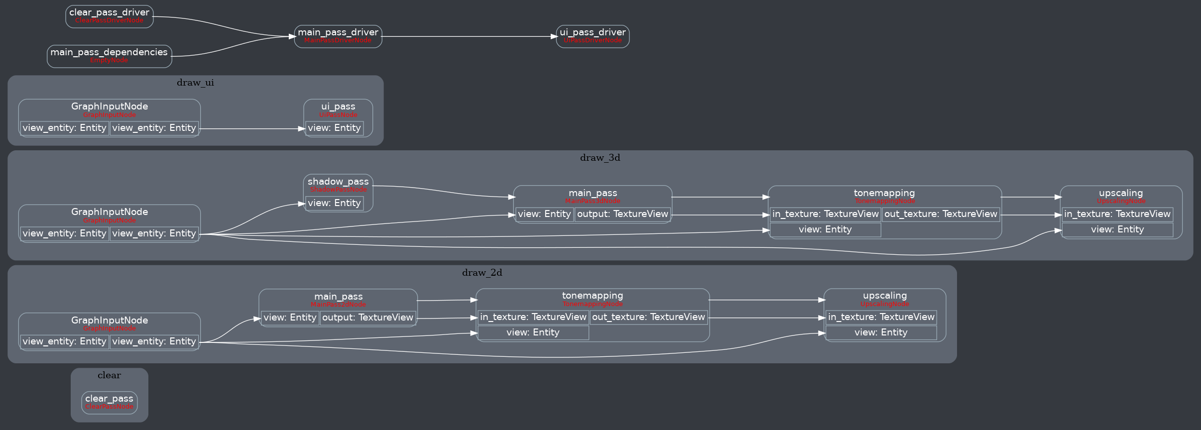
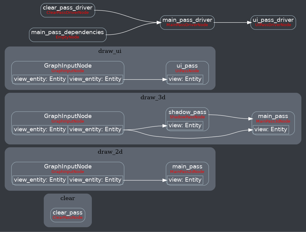
Attempt to make features like bloom #2876 easier to implement. **This PR:** - Moves the tonemapping from `pbr.wgsl` into a separate pass - also add a separate upscaling pass after the tonemapping which writes to the swap chain (enables resolution-independant rendering and post-processing after tonemapping) - adds a `hdr` bool to the camera which controls whether the pbr and sprite shaders render into a `Rgba16Float` texture **Open questions:** - ~should the 2d graph work the same as the 3d one?~ it is the same now - ~The current solution is a bit inflexible because while you can add a post processing pass that writes to e.g. the `hdr_texture`, you can't write to a separate `user_postprocess_texture` while reading the `hdr_texture` and tell the tone mapping pass to read from the `user_postprocess_texture` instead. If the tonemapping and upscaling render graph nodes were to take in a `TextureView` instead of the view entity this would almost work, but the bind groups for their respective input textures are already created in the `Queue` render stage in the hardcoded order.~ solved by creating bind groups in render node **New render graph:**  <details> <summary>Before</summary>  </details> Co-authored-by: Carter Anderson <[email protected]>
|
Pull request successfully merged into main. Build succeeded:
|
Attempt to make features like bloom bevyengine#2876 easier to implement. **This PR:** - Moves the tonemapping from `pbr.wgsl` into a separate pass - also add a separate upscaling pass after the tonemapping which writes to the swap chain (enables resolution-independant rendering and post-processing after tonemapping) - adds a `hdr` bool to the camera which controls whether the pbr and sprite shaders render into a `Rgba16Float` texture **Open questions:** - ~should the 2d graph work the same as the 3d one?~ it is the same now - ~The current solution is a bit inflexible because while you can add a post processing pass that writes to e.g. the `hdr_texture`, you can't write to a separate `user_postprocess_texture` while reading the `hdr_texture` and tell the tone mapping pass to read from the `user_postprocess_texture` instead. If the tonemapping and upscaling render graph nodes were to take in a `TextureView` instead of the view entity this would almost work, but the bind groups for their respective input textures are already created in the `Queue` render stage in the hardcoded order.~ solved by creating bind groups in render node **New render graph:**  <details> <summary>Before</summary>  </details> Co-authored-by: Carter Anderson <[email protected]>
|
|
||
| impl FromWorld for TonemappingPipeline { | ||
| fn from_world(render_world: &mut World) -> Self { | ||
| let tonemap_texture_bind_group = render_world |
There was a problem hiding this comment.
Choose a reason for hiding this comment
The reason will be displayed to describe this comment to others. Learn more.
This is a bind group layout, not a bind group, so the variable name is misleading.
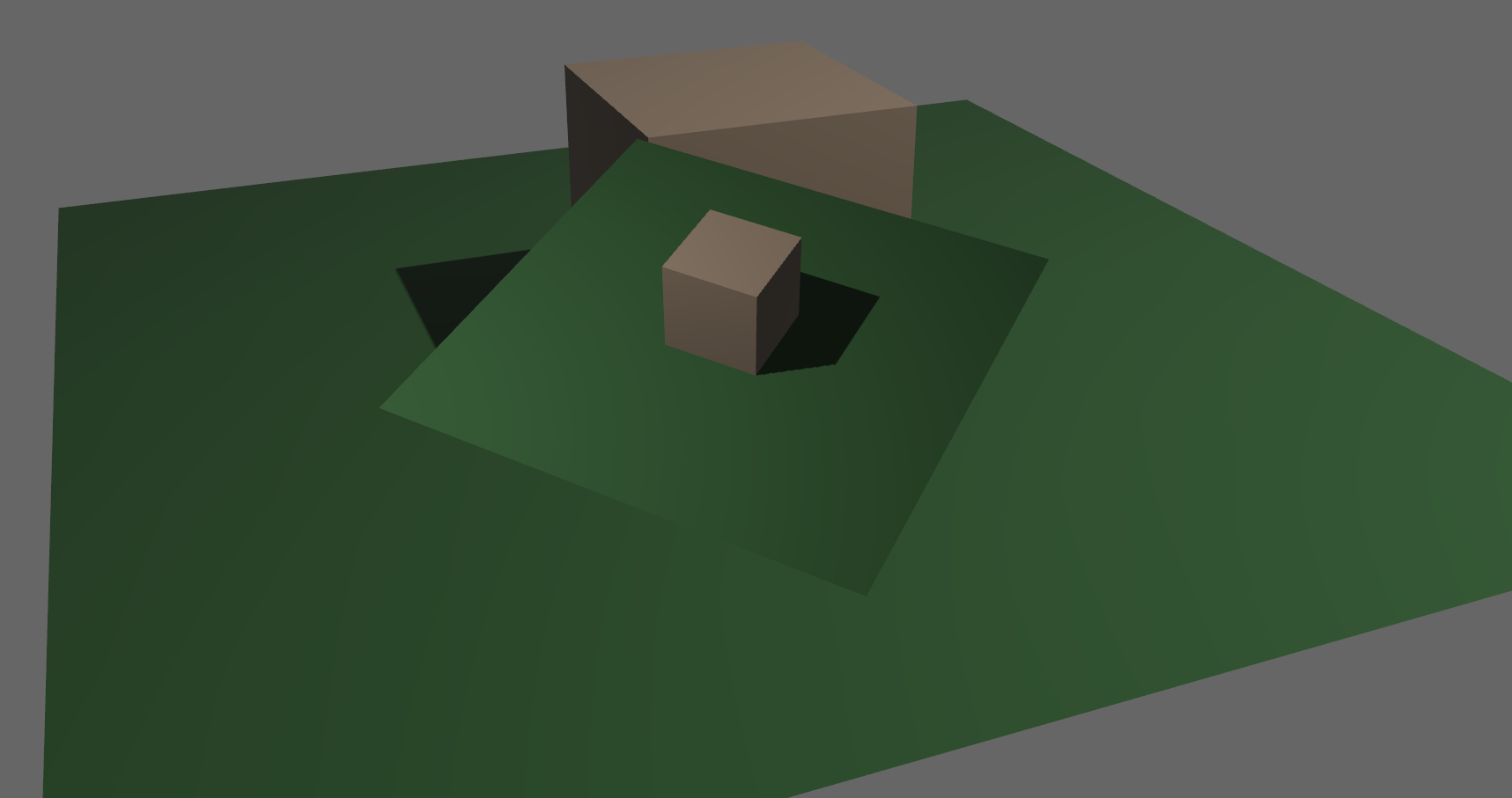
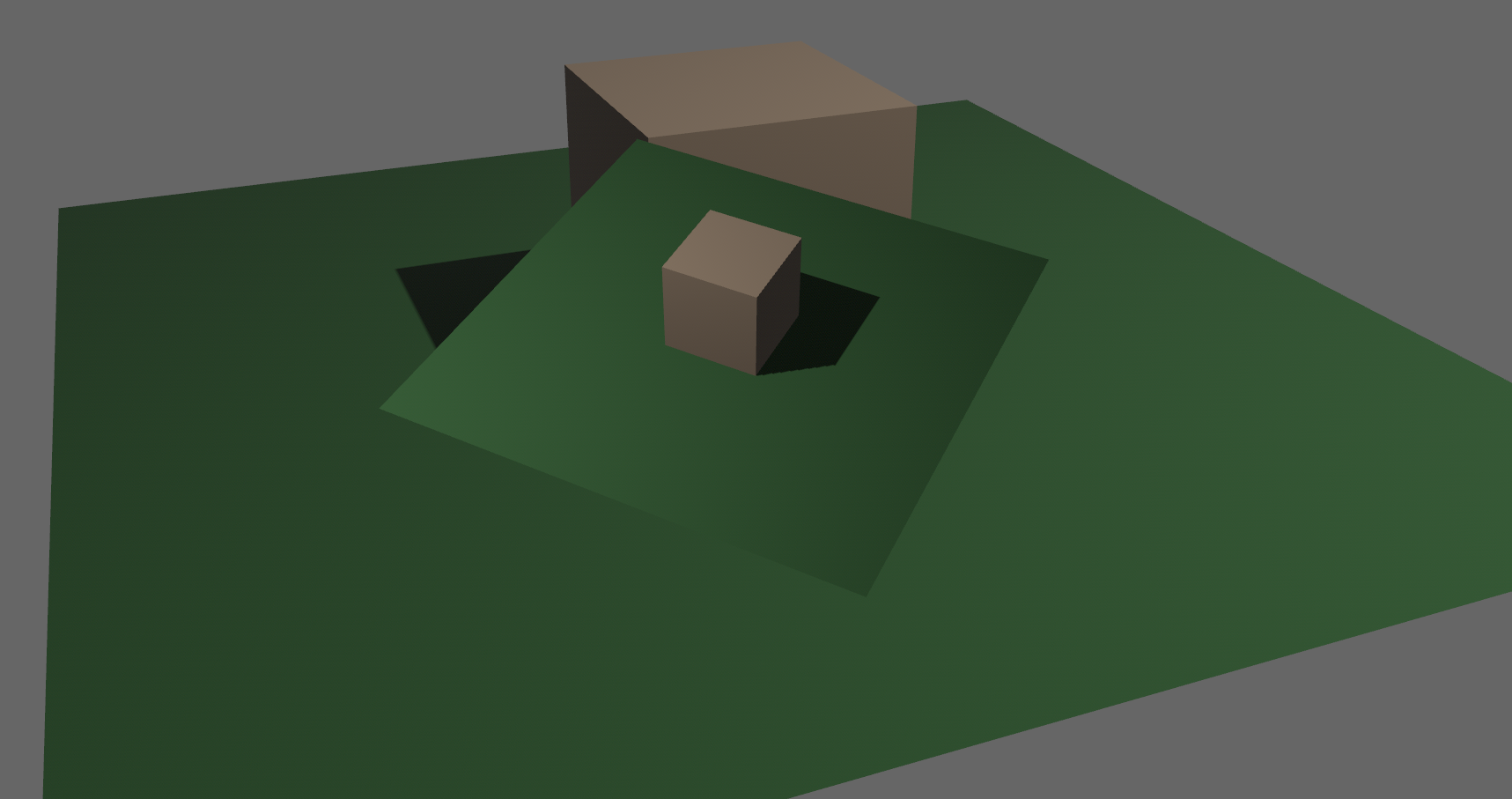
# Objective - Closes #5262 - Fix color banding caused by quantization. ## Solution - Adds dithering to the tonemapping node from #3425. - This is inspired by Godot's default "debanding" shader: https://gist.github.com/belzecue/ - Unlike Godot: - debanding happens after tonemapping. My understanding is that this is preferred, because we are running the debanding at the last moment before quantization (`[f32, f32, f32, f32]` -> `f32`). This ensures we aren't biasing the dithering strength by applying it in a different (linear) color space. - This code instead uses and reference the origin source, Valve at GDC 2015   ## Additional Notes Real time rendering to standard dynamic range outputs is limited to 8 bits of depth per color channel. Internally we keep everything in full 32-bit precision (`vec4<f32>`) inside passes and 16-bit between passes until the image is ready to be displayed, at which point the GPU implicitly converts our `vec4<f32>` into a single 32bit value per pixel, with each channel (rgba) getting 8 of those 32 bits. ### The Problem 8 bits of color depth is simply not enough precision to make each step invisible - we only have 256 values per channel! Human vision can perceive steps in luma to about 14 bits of precision. When drawing a very slight gradient, the transition between steps become visible because with a gradient, neighboring pixels will all jump to the next "step" of precision at the same time. ### The Solution One solution is to simply output in HDR - more bits of color data means the transition between bands will become smaller. However, not everyone has hardware that supports 10+ bit color depth. Additionally, 10 bit color doesn't even fully solve the issue, banding will result in coherent bands on shallow gradients, but the steps will be harder to perceive. The solution in this PR adds noise to the signal before it is "quantized" or resampled from 32 to 8 bits. Done naively, it's easy to add unneeded noise to the image. To ensure dithering is correct and absolutely minimal, noise is adding *within* one step of the output color depth. When converting from the 32bit to 8bit signal, the value is rounded to the nearest 8 bit value (0 - 255). Banding occurs around the transition from one value to the next, let's say from 50-51. Dithering will never add more than +/-0.5 bits of noise, so the pixels near this transition might round to 50 instead of 51 but will never round more than one step. This means that the output image won't have excess variance: - in a gradient from 49 to 51, there will be a step between each band at 49, 50, and 51. - Done correctly, the modified image of this gradient will never have a adjacent pixels more than one step (0-255) from each other. - I.e. when scanning across the gradient you should expect to see: ``` |-band-| |-band-| |-band-| Baseline: 49 49 49 50 50 50 51 51 51 Dithered: 49 50 49 50 50 51 50 51 51 Dithered (wrong): 49 50 51 49 50 51 49 51 50 ```   You can see from above how correct dithering "fuzzes" the transition between bands to reduce distinct steps in color, without adding excess noise. ### HDR The previous section (and this PR) assumes the final output is to an 8-bit texture, however this is not always the case. When Bevy adds HDR support, the dithering code will need to take the per-channel depth into account instead of assuming it to be 0-255. Edit: I talked with Rob about this and it seems like the current solution is okay. We may need to revisit once we have actual HDR final image output. --- ## Changelog ### Added - All pipelines now support deband dithering. This is enabled by default in 3D, and can be toggled in the `Tonemapping` component in camera bundles. Banding is a graphical artifact created when the rendered image is crunched from high precision (f32 per color channel) down to the final output (u8 per channel in SDR). This results in subtle gradients becoming blocky due to the reduced color precision. Deband dithering applies a small amount of noise to the signal before it is "crunched", which breaks up the hard edges of blocks (bands) of color. Note that this does not add excess noise to the image, as the amount of noise is less than a single step of a color channel - just enough to break up the transition between color blocks in a gradient. Co-authored-by: Carter Anderson <[email protected]>
Attempt to make features like bloom bevyengine#2876 easier to implement. **This PR:** - Moves the tonemapping from `pbr.wgsl` into a separate pass - also add a separate upscaling pass after the tonemapping which writes to the swap chain (enables resolution-independant rendering and post-processing after tonemapping) - adds a `hdr` bool to the camera which controls whether the pbr and sprite shaders render into a `Rgba16Float` texture **Open questions:** - ~should the 2d graph work the same as the 3d one?~ it is the same now - ~The current solution is a bit inflexible because while you can add a post processing pass that writes to e.g. the `hdr_texture`, you can't write to a separate `user_postprocess_texture` while reading the `hdr_texture` and tell the tone mapping pass to read from the `user_postprocess_texture` instead. If the tonemapping and upscaling render graph nodes were to take in a `TextureView` instead of the view entity this would almost work, but the bind groups for their respective input textures are already created in the `Queue` render stage in the hardcoded order.~ solved by creating bind groups in render node **New render graph:**  <details> <summary>Before</summary>  </details> Co-authored-by: Carter Anderson <[email protected]>
…5264) # Objective - Closes bevyengine#5262 - Fix color banding caused by quantization. ## Solution - Adds dithering to the tonemapping node from bevyengine#3425. - This is inspired by Godot's default "debanding" shader: https://gist.github.com/belzecue/ - Unlike Godot: - debanding happens after tonemapping. My understanding is that this is preferred, because we are running the debanding at the last moment before quantization (`[f32, f32, f32, f32]` -> `f32`). This ensures we aren't biasing the dithering strength by applying it in a different (linear) color space. - This code instead uses and reference the origin source, Valve at GDC 2015   ## Additional Notes Real time rendering to standard dynamic range outputs is limited to 8 bits of depth per color channel. Internally we keep everything in full 32-bit precision (`vec4<f32>`) inside passes and 16-bit between passes until the image is ready to be displayed, at which point the GPU implicitly converts our `vec4<f32>` into a single 32bit value per pixel, with each channel (rgba) getting 8 of those 32 bits. ### The Problem 8 bits of color depth is simply not enough precision to make each step invisible - we only have 256 values per channel! Human vision can perceive steps in luma to about 14 bits of precision. When drawing a very slight gradient, the transition between steps become visible because with a gradient, neighboring pixels will all jump to the next "step" of precision at the same time. ### The Solution One solution is to simply output in HDR - more bits of color data means the transition between bands will become smaller. However, not everyone has hardware that supports 10+ bit color depth. Additionally, 10 bit color doesn't even fully solve the issue, banding will result in coherent bands on shallow gradients, but the steps will be harder to perceive. The solution in this PR adds noise to the signal before it is "quantized" or resampled from 32 to 8 bits. Done naively, it's easy to add unneeded noise to the image. To ensure dithering is correct and absolutely minimal, noise is adding *within* one step of the output color depth. When converting from the 32bit to 8bit signal, the value is rounded to the nearest 8 bit value (0 - 255). Banding occurs around the transition from one value to the next, let's say from 50-51. Dithering will never add more than +/-0.5 bits of noise, so the pixels near this transition might round to 50 instead of 51 but will never round more than one step. This means that the output image won't have excess variance: - in a gradient from 49 to 51, there will be a step between each band at 49, 50, and 51. - Done correctly, the modified image of this gradient will never have a adjacent pixels more than one step (0-255) from each other. - I.e. when scanning across the gradient you should expect to see: ``` |-band-| |-band-| |-band-| Baseline: 49 49 49 50 50 50 51 51 51 Dithered: 49 50 49 50 50 51 50 51 51 Dithered (wrong): 49 50 51 49 50 51 49 51 50 ```   You can see from above how correct dithering "fuzzes" the transition between bands to reduce distinct steps in color, without adding excess noise. ### HDR The previous section (and this PR) assumes the final output is to an 8-bit texture, however this is not always the case. When Bevy adds HDR support, the dithering code will need to take the per-channel depth into account instead of assuming it to be 0-255. Edit: I talked with Rob about this and it seems like the current solution is okay. We may need to revisit once we have actual HDR final image output. --- ## Changelog ### Added - All pipelines now support deband dithering. This is enabled by default in 3D, and can be toggled in the `Tonemapping` component in camera bundles. Banding is a graphical artifact created when the rendered image is crunched from high precision (f32 per color channel) down to the final output (u8 per channel in SDR). This results in subtle gradients becoming blocky due to the reduced color precision. Deband dithering applies a small amount of noise to the signal before it is "crunched", which breaks up the hard edges of blocks (bands) of color. Note that this does not add excess noise to the image, as the amount of noise is less than a single step of a color channel - just enough to break up the transition between color blocks in a gradient. Co-authored-by: Carter Anderson <[email protected]>

Attempt to make features like bloom #2876 easier to implement.
This PR:
pbr.wgslinto a separate passhdrbool to the camera which controls whether the pbr and sprite shaders render into aRgba16FloattextureOpen questions:
should the 2d graph work the same as the 3d one?it is the same nowThe current solution is a bit inflexible because while you can add a post processing pass that writes to e.g. thesolved by creating bind groups in render nodehdr_texture, you can't write to a separateuser_postprocess_texturewhile reading thehdr_textureand tell the tone mapping pass to read from theuser_postprocess_textureinstead. If the tonemapping and upscaling render graph nodes were to take in aTextureViewinstead of the view entity this would almost work, but the bind groups for their respective input textures are already created in theQueuerender stage in the hardcoded order.New render graph:
Before